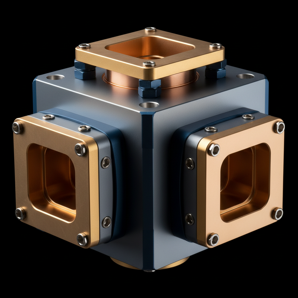
Precision machined waveguide orthomode transducer feed assembly in copper and gold metalwork
Dual Polarized. Deeply Isolated. Precision Machined.

Orthomode Transducers for Every Feed, Band, and Link

Waveguide OMTs for satcom ground stations, radio astronomy observatories, point-to-point mmWave links, and radar systems. Two orthogonal polarizations through one feed, with the isolation and insertion loss the link budget demands.

  • Boifot, turnstile, septum, finline and quad-ridge designs
  • X through W band, WR-90 to WR-10 waveguide interfaces
  • Isolation, insertion loss, XPD and VSWR explained
  • Selection guidance for dual-linear and circular polarization

The fundamentals

What an orthomode transducer does

An orthomode transducer is a polarization duplexer. One waveguide aperture can carry two signals at the same frequency if their electric fields are at right angles to each other, and the OMT is the passive junction that keeps those two signals separate. Its common port, usually square or circular waveguide, supports both orthogonal modes; its two rectangular ports each carry exactly one.

In the feed chain it sits between the feed horn and the electronics. On receive, the horn delivers both polarizations into the common port and the OMT routes each to its own LNB or LNA. On transmit, the power amplifier drives one rectangular port and the signal leaves the horn on that polarization alone. A single antenna can therefore transmit on one polarization while receiving on the orthogonal one, or carry two independent channels at once.

That second trick is polarization reuse: the same spectrum used twice through one dish. It is why dual-polarization feeds are standard practice in satellite communications and point-to-point radio, and why the quality of the OMT, how cleanly it keeps the two channels apart, shows up directly in link capacity.

Why a passive part carries so much weight

Everything behind the OMT trusts it. The receiver assumes transmit energy stays out of its port; each channel assumes the other stays on its own polarization; the link budget assumes the OMT eats almost nothing. Isolation, cross-polar discrimination and insertion loss are the three numbers that say whether those assumptions hold.

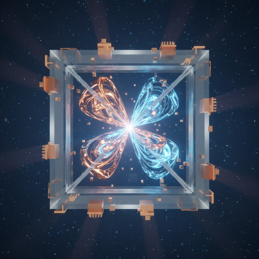
Abstract visualization of two orthogonal polarization planes sharing a single waveguide aperture
Common port
Square or circular waveguide supporting both orthogonal modes, mating to the feed horn.
Through port
Rectangular single-mode waveguide carrying the polarization that passes straight through the junction.
Side port
Rectangular single-mode waveguide extracting the orthogonal polarization from the junction.
Junction
The machined internal geometry, septum, pins, ridges or branching guides, that performs the mode separation.

Architectures

Types of orthomode transducer

Every OMT solves the same problem, but the internal junction geometry sets the trade between bandwidth, isolation, size and cost. These are the architectures you will meet in supplier catalogues and receiver designs.

Branching-junction OMT

The narrowband workhorse

  • A side-coupled branch guide taps one polarization off the common guide while the other passes straight through.
  • Compact, economical, and straightforward to machine.
  • Bandwidth on the order of ten percent, which covers many single-service satcom feeds.

Boifot junction OMT

Wideband, high isolation

  • A symmetric junction using a septum and pins to split one polarization into two paths that are recombined in phase.
  • Covers a full waveguide band with excellent isolation and cross-polar purity.
  • The classic choice for demanding receivers, including radio astronomy front ends.
Precision machined turnstile junction waveguide component with four-fold symmetric ports

Turnstile junction OMT

Four-fold symmetry

  • A four-way symmetric junction splits each polarization into opposing pairs, recombined through matched waveguide networks.
  • The symmetry delivers wide bandwidth and very high polarization purity.
  • Larger and more complex to machine, so it earns its keep where performance governs.
Waveguide septum polarizer component with stepped internal septum for circular polarization

Septum polarizer OMT

Circular polarization, one part

  • A stepped or sloped septum divides a square guide, converting the two rectangular ports directly to left- and right-hand circular polarization at the common port.
  • Combines the polarizer and OMT functions in one compact machined block.
  • Moderate bandwidth, which suits many satcom bands that run circular polarization.
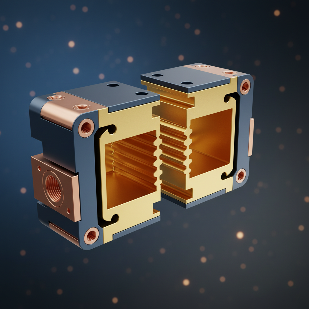
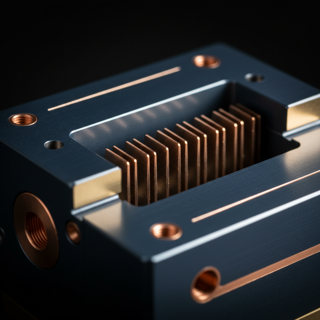
Split-block waveguide assembly with thin internal fins for broadband mode separation

Finline OMT

Thin-fin mode separation

  • Thin metal fins inserted through the guide couple one polarization out while passing the other with little disturbance.
  • Broadband and well suited to split-block construction.
  • A staple of millimeter-wave and cryogenic receiver designs.

Quad-ridge OMT

Multi-octave bandwidth

  • Four ridges in the common guide concentrate the fields and extend single-mode operation across multi-octave spans.
  • The widest bandwidths of any OMT family.
  • Isolation and cross-polar figures are typically more modest, so it appears in wideband instruments more than in frequency reuse links.

Bands and waveguide interfaces

OMTs are built for specific waveguide bands, and the rectangular ports follow the standard WR sizes. These are the bands where dual-polarization feeds are most common.

Common waveguide bands, frequency ranges and WR waveguide sizes for orthomode transducers
BandTypical rangeRectangular waveguideWhere you meet it
X8.2 to 12.4 GHzWR-90Military satcom, radar, deep-space links
Ku12.4 to 18 GHzWR-62VSAT and broadcast satellite services
K18 to 26.5 GHzWR-42Satcom downlinks, point-to-point radio
Ka26.5 to 40 GHzWR-28High-throughput satellites, 5G backhaul
Q33 to 50 GHzWR-22Satcom feeder links, radio astronomy
V50 to 75 GHzWR-15Short-range mmWave links, research
W75 to 110 GHzWR-10mmWave imaging, radar, radio astronomy

Band edges are conventional and vary slightly between references and services. An OMT is specified against its own stated frequency range, not the letter band alone. Suppliers also build band-split OMTs whose two rectangular ports serve different sub-bands, combining polarization and frequency duplexing in one assembly.

Reading the data sheet

The specifications that decide an OMT

A handful of figures determine whether an OMT belongs in your feed. Here is what each one governs, and the trap that goes with it.

Key orthomode transducer specifications, what each one governs, and what to watch for
SpecificationWhat it governsWhat to watch for
Port-to-port isolationHow much signal leaks between the two rectangular ports. In TX/RX systems this is part of what protects the receiver from the transmitter.Check the minimum across the whole band, including the transmit band if you duplex. A midband best-case figure hides band-edge degradation.
Insertion lossSignal lost passing through the OMT. On receive it adds almost directly to system noise temperature; on transmit it is wasted amplifier power turned into heat.Tenths of a dB matter in a receive chain. Compare loss per path, since the through and side paths of some architectures differ.
Cross-polar discrimination (XPD)How cleanly each port couples to its intended polarization only. Sets the interference floor between reused channels.System XPD is limited by the whole chain: antenna, alignment and OMT together. An excellent OMT cannot rescue a badly clocked feed.
Return loss / VSWRThe match at each port. Reflections cause ripple, degrade the amplifier interface, and interact with other feed components.Ask for return loss at all three ports across the band, with the common port terminated the way you will actually use it.
BandwidthThe frequency span over which every other spec is honored, set mainly by the junction architecture.A branching OMT and a turnstile OMT may share a data sheet format but differ several-fold in usable bandwidth. Match the architecture to the span you need.
Power handlingThe peak and average transmit power the structure carries without breakdown or overheating.Ratings derate with altitude and depend on pressurization. Internal features such as septums and pins concentrate fields, so architecture matters here too.
Waveguide size and flange standardMechanical compatibility: WR size, flange family (UG, CPR, UBR and equivalents), and the common port geometry that mates to your horn.A spec-perfect OMT with the wrong flange or an unmatched common port is a machining project, not a component. Confirm interfaces before anything else.
Material, plating and finishConductivity and corrosion resistance, which show up as insertion loss and long-term stability.Aluminum with chromate or silver plating is common; surface finish drives loss at millimeter-wave frequencies. Outdoor feeds need the environmental spec, not just the electrical one.

Achievable figures vary substantially between architectures, bands and manufacturers. Always work from the data sheet of the specific unit, over the specific band, in the specific environment you intend to use it.

Selection

Choosing an OMT for your system

Four decisions narrow the field from every OMT ever made to the two or three worth quoting. Take them in order.

Fix the band and the bandwidth

Your frequency plan sets the waveguide size, and the span you must cover sets the architecture. A single narrow service is branching-OMT territory; a full waveguide band points to a Boifot or turnstile junction; multi-octave instruments need ridged or finline designs. Do not pay for bandwidth the link will never use, and do not assume a narrowband part will stretch.

Settle the polarization scheme

Dual-linear systems use an OMT directly, with mechanical clocking to align the polarization axes. Circular polarization needs either a septum polarizer, compact and elegant at moderate bandwidths, or an OMT behind a separate polarizer where the bandwidth or power requirement is beyond a septum design. The satellite or link plan decides this; the feed follows.

Define the TX/RX duplexing

If the antenna transmits and receives at once, decide how the OMT participates. Same-band systems lean on the OMT's port-to-port isolation. Split-band systems can use a band-split OMT or an OMT with integrated filters so each rectangular port serves its own sub-band. State the transmit power and the acceptable leakage into the receive chain explicitly in the requirement.

Specify the build quality the band demands

Performance at the common junction is symmetry, and symmetry is machining. At Ku-band a standard commercial tolerance serves well; at Ka-band and above, split-block registration, internal tolerances and surface finish separate a 30 dB part from a 50 dB part. For outdoor or airborne feeds, add plating, sealing and the temperature range to the specification rather than assuming them.

What a supplier needs to quote you accurately

  • Frequency range per port
  • Polarization scheme and sense
  • Isolation and XPD targets
  • Maximum insertion loss
  • Return loss / VSWR target
  • Peak and average power
  • Waveguide sizes and flanges
  • Environment and mounting envelope

Where OMTs work

Applications

Anywhere one antenna has to carry two polarizations, there is an OMT behind the horn. Four fields account for most of the demand.

Satellite ground station dish antenna at dusk

Satcom ground stations & VSAT

The volume application. Earth station and VSAT feeds use OMTs to transmit on one polarization while receiving on the other, and to double capacity through polarization reuse. Ku-band services largely run dual-linear, while many Ka-band and government services run circular, so the same dish family may need both plain OMTs and septum polarizer feeds. Isolation and power handling dominate the requirement, since the transmit chain and the LNB share one small assembly behind the dish.

Radio telescope dish array under an open sky

Radio astronomy

Observatories receive both polarizations of astronomical signals that are extraordinarily weak, so every tenth of a dB of insertion loss and every degree of noise temperature counts. Receiver front ends use wideband, symmetric OMTs, Boifot, turnstile and finline designs, often cooled to cryogenic temperatures alongside the LNAs. Bandwidth and loss take priority over power handling, and mechanical designs must survive repeated thermal cycling to tens of kelvin.

Point-to-point mmWave links

Terrestrial microwave and millimeter-wave backhaul doubles link capacity by running two channels on orthogonal polarizations over the same path, a configuration built on the OMT in each terminal's antenna feed. Cross-polar interference cancellation in the modem relaxes the burden somewhat, but the cleaner the feed's XPD, the more margin the link keeps in rain and multipath. Compact integrated OMT-diplexer assemblies are the norm at these frequencies.

Radar & sensing

Polarimetric radar measures how targets scatter horizontally and vertically polarized energy, and weather radar in particular uses the comparison to distinguish rain, hail and snow. Dual-polarization operation runs through OMTs and related junctions in the feed, where high isolation preserves the integrity of the polarimetric measurement and power handling must match the transmitter. Remote sensing instruments and radiometers make similar demands at millimeter-wave bands.

In the feed chain

Integration and care

An OMT that measured beautifully on the bench can still underperform in the field. Almost every case traces to the interfaces: how it was mated, aligned, sealed and verified.

  1. Mate flanges cleanly

    Waveguide joints depend on flat, clean, undamaged mating faces. Inspect for burrs and dents, use the correct gasket or O-ring where the flange type calls for one, and torque fasteners evenly. A poor joint shows up as loss, reflections and, at transmit power, a potential arcing site.

  2. Align the polarization axes

    In dual-linear systems the OMT's orientation sets the polarization the antenna radiates and receives. Clock the feed to the required polarization angle and verify against the far end or the satellite operator's procedure. A small rotational error degrades XPD long before it shows up as signal loss.

  3. Keep water and condensation out

    Outdoor feeds live in rain, humidity and temperature swings. Use pressurization or dry-air systems where the station design provides them, fit the specified windows and seals, and respect drain and desiccant provisions. Moisture inside a waveguide run raises loss and can end a transmitter's day abruptly.

  4. Verify before you blame the link

    A vector network analyzer sweep of insertion loss, return loss and port-to-port isolation, compared against the data sheet, separates a healthy OMT from a damaged one in minutes. Keep the delivered test data with the station records so there is a baseline to compare against later.

  5. Handle it like the precision part it is

    Internal septums, pins and ridges are machined to tight tolerances and do not tolerate dropped tools or improvised probing. Cap open ports during handling and storage, lift by the body rather than a port, and leave internal surfaces alone. Plating scratches and dented flanges are permanent.

RF laboratory bench with waveguide components and test equipment

Confirm before installation

  • Flange types and gasket requirements at all three ports
  • Polarization clocking reference and target angle
  • Pressurization or sealing scheme for the feed run
  • Delivered VNA test data filed with station records
  • Port caps on until the moment of mating

Common questions

Orthomode transducer FAQ

What is an orthomode transducer?

An orthomode transducer, or OMT, is a passive waveguide component that separates or combines two orthogonal linearly polarized signals sharing the same waveguide or antenna feed. It has a common port that supports both polarizations, usually square or circular waveguide, and two single-polarization rectangular ports. In a receive chain it splits the two polarizations arriving from the feed horn so each can go to its own receiver; in a transmit chain it does the reverse.

What is the difference between an OMT, a polarizer and a diplexer?

An OMT separates signals by polarization: two orthogonal polarizations in the same band go to two different ports. A polarizer converts between polarization states, most commonly between linear and circular, without separating channels. A diplexer separates signals by frequency: transmit and receive bands at the same polarization go to different ports. Real feed chains often combine them, for example an OMT behind a polarizer for dual-circular operation, or an OMT with integrated filtering for a TX/RX band split.

Why does port-to-port isolation matter so much?

In a system that transmits on one polarization and receives on the other, the OMT's isolation is part of what keeps the high-power transmit signal out of the sensitive receive chain. Low isolation lets transmit energy leak into the receiver, where it can desensitize the LNA or drive it into compression. In dual-polarization frequency reuse, isolation and cross-polar discrimination together set how cleanly the two channels stay apart, which directly limits how much interference each channel sees from the other.

Do I need dual-linear or circular polarization?

That is set by the system you are joining, not by preference. Most FSS Ku-band satellite services use dual-linear polarization, so a VSAT feed uses an OMT directly. Many Ka-band and military satcom services use circular polarization, which calls for a septum polarizer or an OMT paired with a separate polarizer. Terrestrial point-to-point links commonly run dual-linear for polarization multiplexing. Check the polarization plan of the satellite, link or instrument first; the component choice follows from it.

What do WR designations like WR-28 mean?

WR numbers designate standard rectangular waveguide sizes: the number is the broad wall internal width in hundredths of an inch, so WR-28 is 0.28 inches wide. Each size has a recommended operating band, for example WR-90 for X-band, WR-62 for Ku, WR-28 for Ka, and WR-10 for W-band. An OMT's rectangular ports are specified by WR size plus a flange standard such as UG, CPR or UBR, and mating hardware has to match both.

What isolation and XPD figures should I expect from a good OMT?

Typical commercial OMTs specify port-to-port isolation on the order of 40 dB or better across the band, and high-performance designs such as Boifot or turnstile junctions can reach 50 to 60 dB. Cross-polar discrimination for a well-machined OMT is commonly 30 dB or better. Exact numbers depend on architecture, bandwidth and manufacturing tolerance, so compare specified minima across the full band rather than best-case midband values.

Can an OMT handle transmit power?

Yes. An OMT is a passive metal waveguide structure, and appropriately designed units carry substantial transmit power in earth station and radar feeds. Power handling is limited by voltage breakdown and multipaction at internal features such as septums, pins and ridges, and by thermal dissipation, and it derates with altitude and pressurization state. For transmit applications, confirm both peak and average power ratings for your actual operating environment.

How wide a bandwidth can an OMT cover?

It depends strongly on the architecture. Simple branching or taper junction OMTs typically cover on the order of ten percent bandwidth, which is enough for many single-service feeds. Boifot and turnstile junction designs can cover a full waveguide band, roughly forty percent. Quad-ridge OMTs extend to multi-octave bandwidths at some cost in isolation and cross-polar performance, which is why they appear in wideband instruments more than in frequency reuse links.

Why does machining tolerance matter for an OMT?

An OMT's isolation and cross-polar performance depend on geometric symmetry. Any asymmetry in the common junction converts a little of one polarization into the other, degrading XPD and isolation, and the effect scales with frequency because the structures shrink while tolerances do not. A Ka-band or W-band OMT is a precision machining exercise: split-block halves must register accurately, internal features must hold tight tolerances, and surface finish and plating affect insertion loss.

Can I get an OMT for a non-standard band or a custom interface?

Custom OMTs are routine in this industry. Suppliers regularly quote non-standard band splits, integrated filters for specific TX/RX plans, circular or square common ports sized to a particular horn, non-standard flanges, and cryogenic-compatible designs for radio astronomy receivers. Expect a custom design to need your band edges, polarization scheme, isolation and loss targets, power level, environment, and the mechanical envelope it must fit.

Get a Quote

Tell us about your feed

Send the basics of the requirement and we will point you in the right direction: frequency band, dual-linear or circular polarization, isolation and loss targets, transmit power if any, and the waveguide interfaces at each port.

Specifying a part

Working out which junction architecture fits your band, bandwidth and polarization scheme.

Comparing data sheets

Making sure isolation, XPD and loss figures are compared across the full band on the same basis.

Custom requirements

Non-standard band splits, integrated filtering, custom flanges or cryogenic service.

We use what you submit to respond to your enquiry, which can include sharing it with suppliers who can quote your request. See our privacy notice.